Sludge thermochemical reactor design configurations

Thermochemical reactor design configurations − an overview
A number of different reactor designs have been applied to or trialled for sludge thermochemical treatment processes. They differ mainly in the way in which the sludge solids are mixed and heated within the reactor vessel. The different reactor designs comprise:
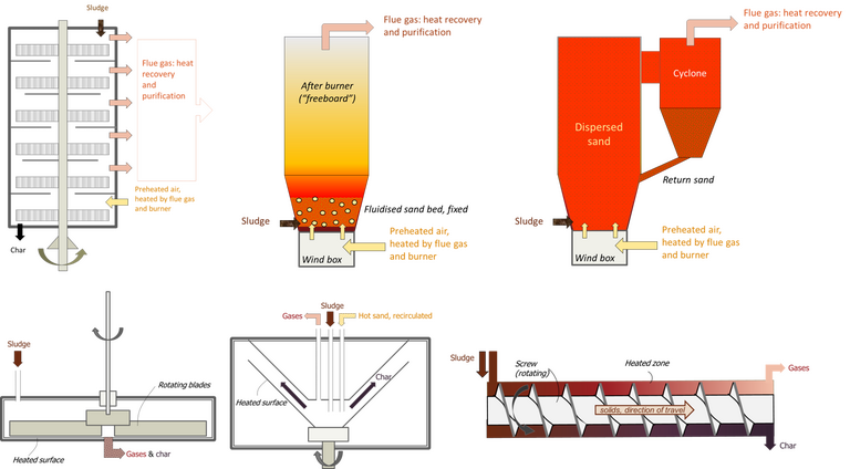
- multiple hearth (Herreshoff) furnace
- fluidised bed (both ‘bubbling’ and circulating)
- ablative
- rotating cone
- auger/screw.
Some of these designs are applicable across more than one of the thermal process types, whereas others are specific to one process.
The auger/screw, ablative and rotating cone reactors are specific to pyrolysis, and have not been widely commercialised. Currently (July 2020) there is only one company offering a rotating cone reactor. There are no examples of commercial auger/screw or ablative reactors, though the auger/screw reactor has been demonstrated at large pilot scale.
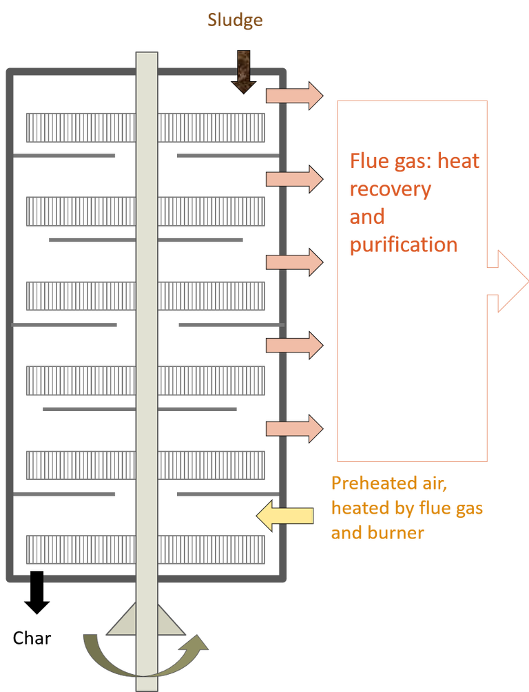
The multiple hearth (or Herreshoff) furnace (MHF) was the original design used for sludge incineration when first implemented in the 1930s. It consists of a series of vertically-stacked circular hearths (i.e. furnace bases).
Herreshoff/multiple hearth incinerator Credit: Judd Water & Wastewater Consultants Herreshoff/multiple hearth incinerator 
The sludge is fed into the top hearth and is moved by the action of revolving arms which move over the surface of each hearth, continuously shifting the solids. This causes the solids to gradually move through the stack via ports in the floor of each hearth or around the periphery of the arms, emerging as a char product at the stack base. The air flows in the opposite direction.
Although there are MHFs still operating (as at July 2020), the design lacks flexibility and is somewhat inefficient. It has since been largely superseded by the more efficient and adaptable fluidised bed reactor design.
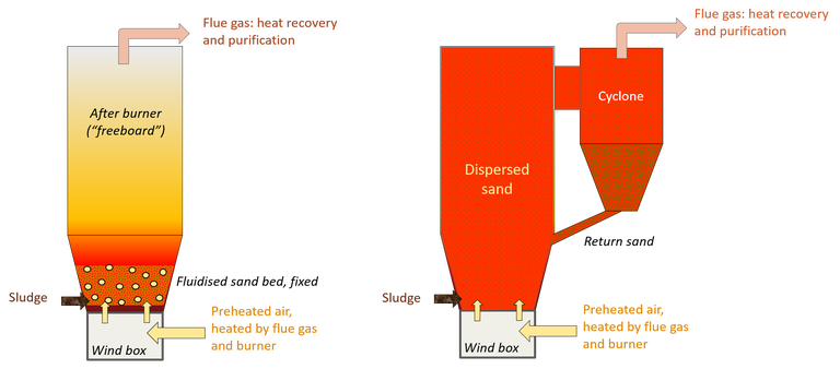
The fluidised bed represents the most widely used reactor configuration for thermochemical treatment of sewage sludge, the bed media being sand. Two designs exist:
- a so-called ‘bubbling’ fluidised bed − in which the sand is fluidised by a stream of gas bubbles at the reactor base, and
- a recirculating bed − where the sand is recirculated through a combustion chamber.
Typical fluidised bed designs: bubbling vs recirculating Credit: Judd Water & Wastewater Consultants Typical fluidised bed designs: bubbling vs recirculating 
The fluidised bed is the preferred configuration for incineration, displacing the original multiple hearth furnaces (MHFs) used in the first sludge incinerators installed in the 1930s. The MHF design was taken from that used by the mining industry for drying/roasting mineral ore concentrates. The fluidised bed configuration, however, was adopted for sludge incineration from the 1960s onwards.
The bubbling fluidised bed (BFB) design comprises a bed of sand sitting on top of a wind box. Pre-heated gas passes into the sand bed from the wind box via nozzles. The gas speed is selected so as to fluidise the sand bed, so that the bed behaves much like a liquid.
The dried, powdered sludge is injected into the bed base and is drawn up through the bed by the passage of the heated gas, the gas being air in the case of the incineration process. In doing so it is thermally converted within the fluidised bed and in the after burner region, referred to as the freeboard, above the bed.
The circulating fluidised bed (CFB) recirculates the sand throughout the entire volume of the reactor. This differs to the BFB where the sand bed is fixed to the base of the reactor.
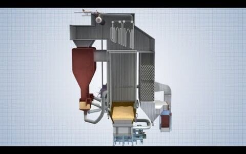
Bubbling vs recirculating bed reactor configurations
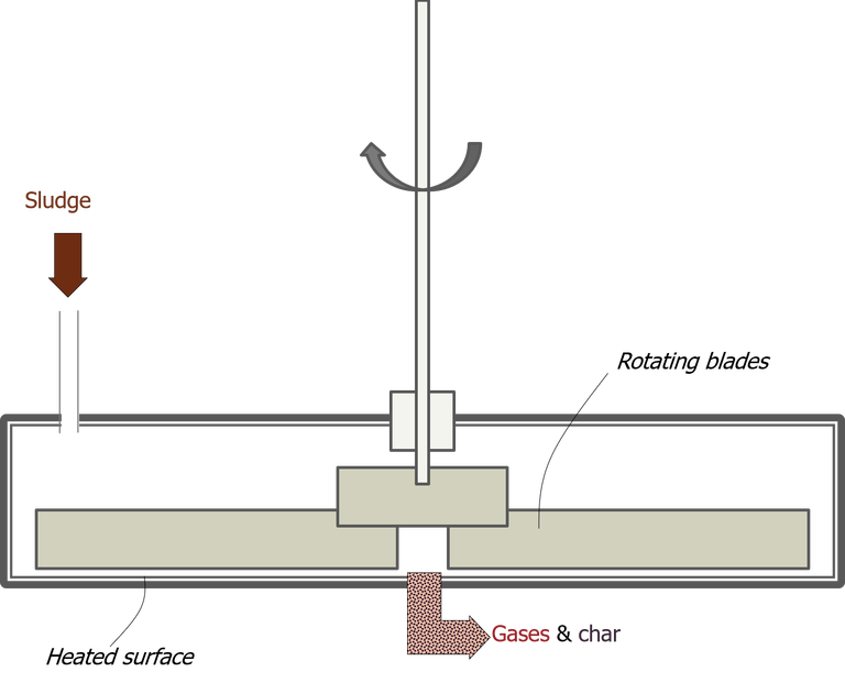
Bubbling vs recirculating bed reactor configurations Source: Convergence Training by Vector Solutions / YouTube The ablative reactor is a fairly recent development, first in the early-mid 1980s, and specific to fast pyrolysis. It is designed so as to reduce the requirement for an inert carrier gas to transport the sludge particles through the reactor: the carrier gas is redundant for non-oxidative thermochemical processes.
The process uses a rotating disc, heated to 600 °C by the hot flue gases, onto which the feed solids are pressed to generate the pyrolytic products. The process is modular in nature: increasing the flow entails increasing the number of reactors, since there is a limit to the extent to which the disc diameter can be increased.
Ablative reactor configuration Credit: Judd Water & Wastewater Consultants Ablative reactor configuration 
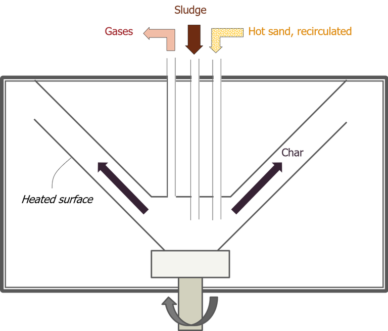
The rotating cone reactor (RCR) technology, owned by BTG in the Netherlands, is another recent development dating back to the early 1990s. The commercialised reactor design combines elements of the ablative reactor with the fluidised bed. Like the ablative reactor, the RCR is modular and has been developed specifically for fast pyrolysis.
The reactor comprises a cone base with a second cone placed above it, forming an annular gap. The biomass solids and preheated sand grains are fed into the centre of the heated rotating cone base. Both the sand and solids then pass up along the annular gap in a spiral motion under the influence of centrifugal forces. While passing through the reactor in this spiral motion, the biomass undergoes pyrolysis.
Rotating cone configuration Credit: Judd Water & Wastewater Consultants Rotating cone configuration 
The auger or screw reactor uses a screw mechanism to transport the sludge along the horizontal length of the reactor. This means that, as with the ablative and cone reactors, there is no need for an inert carrier gas since the sludge particles are conveyed mechanically. The rate of pyrolysis (slow to fast) can in part be controlled by the rotation rate of the screw, since this is directly proportional to the reactor residence time.
As of July 2020, there are no commercial processes based on this configuration, though several large-scale demonstration trials have been reported.
Auger/screw reactor configuration Credit: Judd Water & Wastewater Consultants Auger/screw reactor configuration 
The most commonly employed reactor design is the fluidised bed, which is used for both sludge drying and incineration applications.


